|
|
 |
 |
 |
| |
Oscillation
Frequency and Load Capacitance |
| |
In
an oscillation circuit in which a quartz resonator works as
inductive impedance, the equivalent circuit is indicated by
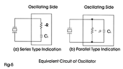
the engative resistance and capacitance, as shown in Fig. 5.
Fig. 5 (a) expresses the oscillation circuit with a series circuitry,
while (b) expresses a parallel circuitry.
Here the capacitance CL is an effective capacitance when the
oscillating side is viewed from the ends of the quartz resonator,
usually called a load capacitance, and -R and - p are negative
resist-ances of the oscillating side.
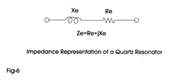
In this type of oscillation circuit, the quartz resonator works
as a series circuitry of an inductive reactance Xe and a resistance
Re, as shown in Fig.6 and its oscillation frequency is expressed
by:

The conditions for oscillation to start is 1 Re 1 < 1 R 1
in the case of (a), and 1 Rp 1 > 1 p 1 in the case of (b),
where Re is the series resonant resistance (equivalent series
resistance) of the series circuitry of a quartz resonator and
capacitance CL, and Rp is the parallel resonant resistance (equivalent
parallel resistance) of the parallel circuitry of quartz resonator
and capacitance CL.
In order to have certain oscillation while increase of the equivalent
resistance at a low excited level of the quartz resonator is
taken into consideration, the negative resistance (-R) of the
circuit must be good deal larger compared with Re.
Thus the oscillation frequency is decided by the electrical
equivalent constant of the quartz resonator and the load capacitance
of the oscillating side regardless of configuration of the oscillation
circuit (operating temp. and exciting level to be specified
separately), so that the load capacitance of the oscillation
circuit must be defined clearly at the time of manufacture or
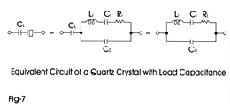
use. The equivalent circuit of the quartz resonator and a series
connected load capacitance CL is expressed AS in Fig. 7, and
constants at this time are as follows:

The oscillation frequency at this time is increased by ¡µf,
and we have:

where ¡µf is the difference from the frequency Fo in series
resonance. Re-arrangement of this equation will yield the following
equation:

Where CO/C1 is called the capacitance ratio, The capacitance
ratio serves as a reference for knowing the size of the amount
of change in the oscillation frequency due to alteration of
the load capacitance. |
| |
 |
 |
| |
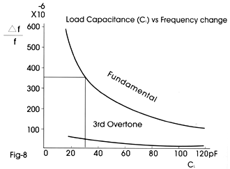
 Fig 8 shows the load capacitance vs frequency change ratio characteristic
of a fundamental AT cut resonator and a 3rd overtone resonator.
It is required, as shown by the Fig 8 to use a fundamental resonator
and select a small load capacitance in order to obtain the amount
of change over a wide frequency range through changing of the
load capacitance. |
| |
 |
|
|

