|
|
 |
 |
 |
| |
General
Information--Crystal Units |
| |
 AT Cut Crystals
For precise frequency control in radio
and line communication systems, quartz crystal resonators have
proved indispensable. The material properties of crystalline
quartz are such that quartz resonators display stabilites and
Q factors that cannot be matched by other types of resonator
over a frequency range from a few 1 MHz to 200 MHz.
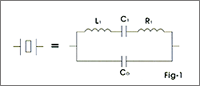
Equivalent
Circuit
Fig-1 shows the conventionally accepted equivalent circuit of
a crystal resonator at a frequency near its main mode of vibration.
The inductance Ll reperesents the vibrating mass, the series
capacitance Cl the compliance of the quartz element and the
resistance Rl the internal frication of the element, mechanical
losses in the mounting system and accoustial losses to the surrounding
environment.
The
shunt capacitance Co is made up of the static capacitance
between the electrodes, together with stray capacitances of
the mounting system.
|
| |
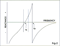
 There
are two zero-phase frequencies associated with this simple circuit,
one is at series resonance fs, another at antiresonance fa.
When used in an oscillator, crystal units will operate at any
frequency within the broken lines There
are two zero-phase frequencies associated with this simple circuit,
one is at series resonance fs, another at antiresonance fa.
When used in an oscillator, crystal units will operate at any
frequency within the broken lines
of Fig-2 as determined by the phase of the maintaining circuit. |
| |
 |
By variation of this reactive condition, the crystal frequency
may be trimmed to a limmed extent. The degree to which this
frequency may be varied (frequency pulling) is inversely proportional
to the capacitance ratio. |
| |
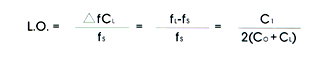
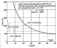
Load
Capacitance
Many 1 practical oscillator circuits make use of a load capacitor
CL in series or parallel with the crystal, either in order to
provide a means for final frequency adjustment, or perhaps for
modulation or temperature compensation purposes. The presence
of the load capacitor shifts the operating frequencyof the crystal
byan amountdependent onthevalue of CLandthevaluesof CO and Cl.
Thefractional difference in frequency between the load resonance
frequency FLand the series resonance frequency Fs is known as
the load resonance frequency offset (L.O.).
 |
| |
Frequency
Pulling
In many applications a variable capacitor (trimmer)
is used as the load reactive element to adjust the frequency.
The fractional freqency range available between specified values
of this load reactive element is called the pulling range (RR.)
and it can be calculated by using the following formula:
 |
| |
|
| |
Sensitivity
A useful parameter to the design engineer
is the pulling sensitivity (S) at a specified value of load
capacitance. It is defined as the incremental fractional frequency
change for an incremental change in load capacitance. It is
normally expressed in ppm/pf (10-6/pf) and can be calculated
from the formula:
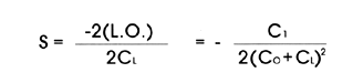
It is very important to define the mean load capacitance to
enable the actual crystal frequency to fall within the tolerances
of the specified nominal frequency. It is also important to
use, wherever possible, standard values of load capacitance;
for example:2Opf, 3Opf.
Fig-3 shows the relationship between 1.0.; RR. and S. |
| |
 |
| |
Frequency
Pulling Calculation
An approximation to the pulling for any crystal can be calculated
from this simple formula:
 |
| |
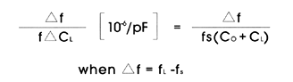
Resistance
The equivalent circuit of the crystal has one
other important parameter: This is RI, the motional resistance.
This parameter controls the Q of the crystal unit and will define
the level of oscillation in any maintaining circuit. The load
resonance for a given crystal unit depends upon the load capacitance
with which that unit is intended to operate. The frequency of
oscillation is the same in either a series or parallel connection
of the load capacitance.
If the external capacitance is designated the load resonance
resistance may be calculated as follows:
The equivalent shunt or parallel resistance at load resonance
frequency is approximately:

It should be remembered that Rl does not change thus the effective
parameters of any user network can be readily calculated. |
| |
Frequency
Temperature Characteristics
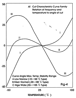 The AT-cut crystal has a frequency temperature characteristic
which may be described by a cubic function of temperature. This
characteristic can be precisely controlled by small variations
in the exact angle at which the crystal blank is cut from the
original quartz bar. Fig,4 illustrates some typical cases. This
cubic behaviour is in contrast to most other crystal cuts, which
have parabolic temperature characteristics.
The AT-cut crystal has a frequency temperature characteristic
which may be described by a cubic function of temperature. This
characteristic can be precisely controlled by small variations
in the exact angle at which the crystal blank is cut from the
original quartz bar. Fig,4 illustrates some typical cases. This
cubic behaviour is in contrast to most other crystal cuts, which
have parabolic temperature characteristics.
As a consequence, the AT-cut is generally the best choice when
specifying a unit to operate over a wide temperature range,
and is available in a range of frequencies from 1 to 200 MHz.
|
|
|